Development boards marketed as “multi-protocol” usually ship with a folder of disconnected Arduino sketches — one per peripheral, none of them production-ready. You get blinking LEDs and serial prints, but nothing that exercises LoRa, Ethernet, CAN, and BLE simultaneously on the same SPI bus while maintaining a responsive touch UI. The gap between a vendor demo and usable firmware is months of integration work: managing shared bus contention, async probe scheduling, persistent state, and display rotation without tearing.
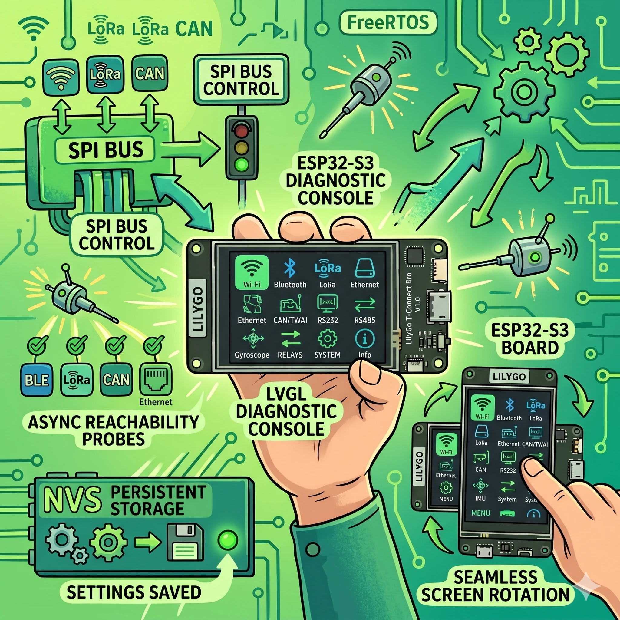
This LilyGo T-Connect Pro ESP32-S3 firmware closes that gap. It is a PlatformIO project that turns the T-Connect Pro V1.0 board into a fully operational touch-driven LVGL diagnostics console with eleven live pages — covering Wi-Fi, BLE, LoRa, Ethernet (W5500), CAN/TWAI, RS232, RS485, IMU, relay control, and system settings. All six wired and wireless protocols run concurrently on the same shared SPI bus, with FreeRTOS tasks handling asynchronous reachability probes, and every user preference persisted to NVS across reboots. The repository is private — access is available by request.
- Why This Firmware Exists
- Hardware Architecture
- Pin Map and Bus Sharing
- Memory Layout
- Software Stack
- Code Organization
- Initialization Sequence
- The Eleven-Page LVGL Console
- System Pages
- Sensor and Input Pages
- Protocol Pages
- Control and Settings Pages
- Protocol Implementation Details
- LoRa: SX1262 via RadioLib
- Ethernet: W5500 Outside lwIP
- CAN: TWAI in Classic Mode
- BLE: Deferred Bluedroid Scanner
- Asynchronous Reachability Probes
- Persistent State and NVS
- Display and touch
- Top bar and navigation
- Ota and time sync
- Build and flash
- Vendored Libraries and Licensing
- Related Projects
- Frequently Asked Questions
- Is the repository public?
- Does the firmware support CAN-FD?
- Can I use a different LoRa frequency?
- Why is BLE initialization delayed?
- What board variants are supported?
- How does Ethernet coexist with Wi-Fi?
- Need a consultation?
Why This Firmware Exists
The LilyGo T-Connect Pro packs an ESP32-S3-R8 (16 MB flash, 8 MB PSRAM), a 222×480 capacitive touch display, an SX1262 LoRa radio, a W5500 Ethernet controller, a CAN-FD transceiver, RS232 and RS485 transceivers, a BMA423 accelerometer, and a 10 A relay — all on a single board. LILYGO’s official repository provides fragmented examples that initialize each peripheral in isolation. None of them handle the shared SPI bus correctly when multiple peripherals are active, and none provide a UI beyond serial output.
This LilyGo T-Connect Pro ESP32-S3 firmware was built to validate every on-board peripheral simultaneously, serve as a hardware acceptance test, and provide a production-quality starting point for OEM projects. Rather than twelve separate sketches, you get one firmware that boots into a polished eleven-page LVGL console in under three seconds.
Hardware Architecture
The T-Connect Pro V1.0 runs an ESP32-S3-R8 clocked at 240 MHz with 8 MB of octal PSRAM. The board concentrates six communication protocols on a single SPI bus shared between the ST7796 display, SX1262 LoRa module, and W5500 Ethernet controller, each isolated by dedicated chip-select lines on GPIOs 21, 14, and 10 respectively.
Pin Map and Bus Sharing
The shared SPI bus architecture is the most critical design constraint. All three CS lines must be parked HIGH before any SPI transaction to prevent crosstalk. The firmware handles this at the very first line of peripheralsBegin() — before display initialization, before LoRa, before Ethernet. A single CS line floating low during another peripheral’s transaction corrupts both transfers silently.
| Peripheral | Interface | Key GPIOs |
|---|---|---|
| ST7796 Display | SPI (shared) | CS=21, DC=45, RST=42, BL=46 |
| SX1262 LoRa | SPI (shared) | CS=14, RST=41, BUSY=40, DIO1=39 |
| W5500 Ethernet | SPI (shared) | CS=10, RST=9, INT=13 |
| CST226SE Touch | I2C (400 kHz) | SDA=15, SCL=16, RST=48, INT=11 |
| BMA423 IMU | I2C (shared) | Addr 0x18 or 0x19 |
| CAN (TWAI) | Native TWAI | TX=6, RX=7 |
| RS232 | UART1 | TX=4, RX=5 |
| RS485 | UART2 | TX=17, RX=18 |
| Relay | GPIO | GPIO=8 (active HIGH) |
Memory Layout
ESP32-S3 internal DRAM is tight when Wi-Fi, BLE, and lwIP are all active. The firmware routes all LVGL allocations to PSRAM through a custom allocator, freeing roughly 96 KB of internal DRAM for FreeRTOS task stacks. Two display draw buffers (222×60×2 bytes each, about 52 KB total) also reside in PSRAM. Since UI widgets are allocated once at boot and rarely freed, PSRAM latency is acceptable — there are no allocation hot paths in the render loop.
Software Stack
The LilyGo T-Connect Pro ESP32-S3 firmware is built with PlatformIO on the Arduino framework (espressif32 platform 6.5.0, Arduino-ESP32 core 2.0.14). It uses LVGL 8.4.0 for the UI, RadioLib 7.1.2 for LoRa, and the vendored Ethernet 2.0.0 library for W5500 — kept separate from lwIP to avoid routing conflicts with the ESP32’s native Wi-Fi stack.
Code Organization
The entire codebase is approximately 2,700 lines spread across four source files and five headers. The split is deliberate: hardware drivers never call UI functions, and the UI never blocks on I/O.
| File | Lines | Responsibility |
|---|---|---|
| main.cpp | 36 | Orchestration: peripheralsBegin → probesBegin → uiBegin, then tick loop |
| peripherals.cpp | 511 | All hardware drivers, protocol stacks, NVS persistence |
| ui.cpp | 1,481 | LVGL init, 11 page builders, navigation, top-bar state |
| probes.cpp | 173 | FreeRTOS probe worker task — ICMP and TCP reachability |
Initialization Sequence
The boot sequence is strictly linear — no parallel initialization. This is intentional: shared-bus peripherals need deterministic CS line states, and BLE’s Bluedroid stack requires the Wi-Fi radio to have completed its initial association before Bluetooth coexistence can stabilize. The full sequence runs in about 2.5 seconds on cold boot.
- Park all SPI CS lines HIGH (display, LoRa, Ethernet)
- Load NVS namespace “tcpro” — relay state, rotation, brightness, boot count, best uptime
- Initialize relay GPIO from saved state
- ST7796 display bring-up with rotation and PWM backlight
- RS232 and RS485 UART initialization at 115200 baud
- I2C bus at 400 kHz — CST226SE touch init, full bus scan (0x08–0x77), BMA423 probe
- SPI bus — SX1262 LoRa init (868 MHz, SF9, +10 dBm), W5500 reset pulse + DHCP start
- TWAI driver install (500 kbps, normal mode)
- Wi-Fi STA connect, AP scan results captured
- Deferred BLE task: waits for Wi-Fi association or 8-second timeout, then 1.5-second grace, then Bluedroid init
- Async probe FreeRTOS task created
- LVGL init with PSRAM allocator, display and touch driver glue, 11 pages built
The Eleven-Page LVGL Console
The console is the primary interface. Every page updates every 250 ms from background state — no blocking I/O in the UI loop. Navigation works by horizontal swipe gesture, top-bar arrow buttons, or the physical BOOT button (GPIO 0). The current page index persists to NVS, so the firmware resumes exactly where you left it after a power cycle.
System Pages
CHIP — CPU model, flash and PSRAM sizes, free heap, SDK version, MAC address, CPU temperature, reset reason, boot count (all-time NVS counter), best uptime (5-minute save resolution), nearby AP count from boot scan, and a live backlight level indicator.
WIFI — SSID, connection state, RSSI strength, channel, assigned IP, gateway, DNS, BSSID, OTA readiness status. Three ICMP reachability probes fire every 3 seconds while this page is visible: gateway, DNS server, and 1.1.1.1. Probes pause when you swipe away to avoid wasting CPU cycles.
BLE 5 — Bluedroid stack mode, advertisement count, unique device count (up to 32), latest discovered device name and RSSI, and a top-by-RSSI device list. The BLE scanner starts with a deliberate delay after Wi-Fi to prevent radio coexistence crashes.
Sensor and Input Pages
TOUCH — CST226SE controller ID, live finger count, X/Y coordinates, and a pressure magnitude bar. Useful for verifying touch calibration and multi-finger detection on the capacitive panel.
IMU — BMA423 accelerometer: live X, Y, Z acceleration values, vector magnitude, chip temperature. Also displays a full I2C bus inventory (all addresses responding on the bus), regardless of whether the BMA423 is physically present. The IMU page updates every 100 ms when the sensor is detected.
Protocol Pages
LoRa — SX1262 configuration dump (868 MHz, SF9, 125 kHz BW, +10 dBm), TX beacon counter, RX packet counter, CAD (Channel Activity Detection) state, and the last received payload with RSSI and SNR. The radio transmits a beacon every 5 seconds and runs CAD scanning every 2 seconds.
ETH — W5500 probe result, link state, DHCP-assigned IP, gateway, DNS, and a locally-administered MAC derived from the ESP32 Wi-Fi MAC. TCP reachability probes to gateway and DNS fire every 3 seconds when visible. These use raw TCP connect on the W5500 stack — not lwIP — because the Ethernet controller operates outside the ESP32’s native TCP/IP stack.
CAN — TD501MCANFD transceiver info, TWAI driver state, bus state (error-active, error-passive, bus-off), TX/RX/TX-fail counters, and the last received frame ID with hex data dump. The firmware sends a heartbeat frame (ID 0x123, 8-byte payload with counter and timestamp) every second.
UART — RS232 (TD501D232H) and RS485 (TD501D485H-A) side by side: transceiver chip, pin map, baud rate, TX/RX byte counters, and the last received byte. Both ports transmit a heartbeat character (*) every second and continuously drain their receive buffers.
Control and Settings Pages
RELAY — Controls the 10 A SPST relay on GPIO 8. A persistent toggle switch saves the state to NVS immediately — the relay returns to its last state after any power cycle. Also tracks a total click counter.
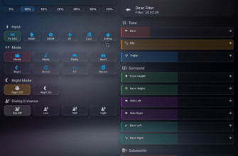
SETTINGS — Display rotation (0°/90°/180°/270° with live layout reflow), auto-page-switch interval (OFF, 10, 15, 20, 30, or 60 seconds), color inversion toggle, and brightness stepper (range 20–255, step 15, live preview). All settings write to NVS on change.
Protocol Implementation Details
LoRa: SX1262 via RadioLib
The SX1262 radio is configured for 868 MHz, spreading factor 9, 125 kHz bandwidth, coding rate 4/7, and a private sync word (0x14). TX power is +10 dBm. The firmware implements a simple beacon protocol: every 5 seconds it transmits a string payload (“TCpro #<counter>”), and between transmissions it performs Channel Activity Detection every 2 seconds to check for incoming packets. Received payloads are displayed with RSSI and SNR on the LoRa page.
The critical detail is SPI bus sharing. Before every RadioLib transaction, the display and Ethernet CS lines must be parked HIGH. RadioLib handles its own CS assertion, but if the display driver left its CS low after an incomplete DMA transfer, the LoRa transaction would be corrupted. The firmware guarantees CS parking at init time and trusts the Arduino_GFX library to deassert after each display operation.
Ethernet: W5500 Outside lwIP
The W5500 Ethernet controller runs on the vendored Ethernet 2.0.0 library, deliberately kept outside the ESP32’s lwIP TCP/IP stack. This is a design choice, not an oversight: if the W5500 were integrated into lwIP, routing table conflicts between the Wi-Fi and Ethernet interfaces would cause packets to take unpredictable paths. By keeping the W5500 on its own stack, Wi-Fi traffic stays on the ESP32’s native netif, and Ethernet traffic uses the W5500’s independent socket layer.
The W5500 requires a hardware reset pulse before initialization — a quirk of the board integration. The firmware toggles the reset pin (GPIO 9) for 50 ms, then derives a locally-administered MAC from the ESP32’s Wi-Fi MAC and starts DHCP. TCP reachability probes on the ETH page use the W5500’s own EthernetClient.connect() rather than esp_ping, since ICMP is not available on the non-lwIP stack.
CAN: TWAI in Classic Mode
The board carries a TD501MCANFD transceiver that supports CAN-FD, but the firmware runs the ESP32-S3’s native TWAI controller in classic CAN mode at 500 kbps. CAN-FD requires the data phase to use a separate, higher bitrate — a feature the ESP32-S3 TWAI peripheral does not support in hardware. The firmware installs the TWAI driver with normal mode (not listen-only), sends a heartbeat frame with ID 0x123 every second, and continuously drains the RX queue, displaying the last received frame on the CAN page.
BLE: Deferred Bluedroid Scanner
BLE initialization is the most nuanced. On ESP32-S3, the Wi-Fi and Bluetooth radios share the same 2.4 GHz PHY. Starting Bluedroid before Wi-Fi has completed its initial association causes radio arbitration failures that manifest as either Wi-Fi disconnects or Bluetooth crashes. The firmware solves this by spawning a FreeRTOS task that waits for WL_CONNECTED (or an 8-second timeout if Wi-Fi credentials are invalid), then adds a 1.5-second grace period before initializing Bluedroid in scanner-only mode.
The scanner runs in active mode (160 ms interval, 150 ms window) and tracks up to 32 unique devices by MAC address, storing name and RSSI for each. No connections or pairing are established — this is purely for passive environment monitoring.
Asynchronous Reachability Probes
Network reachability probes are inherently blocking — an ICMP ping waits for a reply or timeout, and a TCP connect either succeeds or times out after several seconds. Running these in the main loop would freeze the LVGL UI. The firmware handles this with a dedicated probeWorker FreeRTOS task running on a 4 KB stack, consuming probe requests from a FreeRTOS queue.
The main loop checks which page is currently visible. If it is the WIFI page and Wi-Fi is connected, it enqueues ICMP probes to the gateway, DNS server, and 1.1.1.1. If it is the ETH page and Ethernet is linked, it enqueues TCP connect probes to the Ethernet gateway and DNS. When the user swipes to a different page, no new probes are enqueued — the worker drains its queue and idles. This saves both CPU time and network bandwidth when the user is looking at the LoRa or CAN page.
Wi-Fi ICMP probes are pinned to the WIFI_STA_DEF netif to prevent the kernel from routing them over the W5500 interface. Without this pinning, the ESP32 routing table could send ICMP packets out the Ethernet interface if both are connected, giving false positive results on the Wi-Fi page.
Persistent State and NVS
The firmware uses a single NVS namespace (tcpro) to persist user preferences and operational counters across reboots. The following values survive power cycles:
- Relay ON/OFF state and total click counter
- Display backlight level (20–255)
- Display rotation (0°, 90°, 180°, 270°)
- Auto-page-switch interval (OFF or 10–60 seconds)
- Color inversion flag
- Last visible page index
- All-time boot counter
- Best uptime (saved at 5-minute granularity to reduce flash wear)
NVS writes are throttled where possible. The best-uptime value, for example, is only written to flash every 5 minutes — not every tick. Relay state and settings changes write immediately because user intent must not be lost if power is cut a second later.
Display and touch
The ST7796 display runs at 222×480 resolution with a PWM backlight on LEDC channel 1 at 2 kHz. The firmware supports all four rotation modes. When the user changes rotation in the Settings page, the display driver rotates its output, the touch coordinate transformation matrix updates to match, and the page layout reflows — half-width rows switch between 48% and 100% width depending on landscape or portrait orientation.
The CST226SE capacitive touch controller runs on the I2C bus at 400 kHz. The LVGL touch driver reads coordinates only when a finger is present (interrupt-driven detection). The controller supports multi-finger and pressure detection, both of which are exposed on the TOUCH page.
Top bar and navigation
The top bar spans two rows. The first row contains previous/next navigation buttons, the current page index and title, and a shortcut to the Settings page. The second row shows live status badges: Wi-Fi (color-coded by connection state), Ethernet link state, BLE unique device count, LoRa TX count, and a wall-clock time (synced via SNTP to pool.ntp.org and time.google.com after Wi-Fi connects — displays --:--:-- until sync completes).
Navigation responds to horizontal swipe gestures anywhere on the screen, the top-bar arrow buttons, and the physical BOOT button (GPIO 0, which advances to the next page). An optional auto-switch timer rotates through pages at a configurable interval, useful when the board is mounted as a passive monitoring display.
Ota and time sync
ArduinoOTA starts after Wi-Fi connects, advertising the hostname t-connect-pro.local. The OTA status is displayed on the WIFI page. SNTP time sync queries pool.ntp.org and time.google.com, with a configurable time zone offset (default UTC+3, adjustable via state.tz_offset_sec in app_state.h). After sync, the top bar displays the current time; before sync, it shows a placeholder.
Build and flash
The project uses PlatformIO with a custom board definition (boards/esp32s3_flash_16MB.json) targeting the ESP32-S3 at 240 MHz with 16 MB QIO flash and 8 MB OPI PSRAM. Upload speed is 921600 baud.
git clone https://github.com/ilia-ae/lilygo-t-connect-pro.git
cd lilygo-t-connect-pro
cp include/secrets.h.example include/secrets.h
# Edit secrets.h with your Wi-Fi credentials
pio run -t upload
pio device monitor
Wi-Fi credentials go in include/secrets.h (gitignored). If the file is missing, the firmware compiles with placeholder credentials and emits a compiler warning — it will boot and show all pages, but Wi-Fi and time sync will not function. For recovery after a bad flash, hold the BOOT button while pressing reset, then re-flash. The repository is private — access is available by request for those interested in the LilyGo T-Connect Pro ESP32-S3 firmware.
Vendored Libraries and Licensing
Two libraries are vendored in the lib/ directory rather than pulled as PlatformIO dependencies. The Ethernet 2.0.0 library (LGPL-2.1+) is vendored to maintain separation from the lwIP W5500 stack that some ESP32 board packages include. The Arduino_DriveBus library (GPL-3.0, LILYGO private) handles CST226SE touch initialization and I2C bus operations — it is not available in the public PlatformIO registry. RadioLib, LVGL, Arduino_GFX, and SensorLib are pulled from the registry as standard dependencies. Full licensing details are in THIRD_PARTY_NOTICES.md.
Related Projects
If you are working with ESP32 and BLE beacons, the BLE.KZ presence tracking ecosystem covers a complementary approach using ESPHome firmware with dual beacon protocols and a Flutter companion app. For e-ink display integration with ESPHome, the M5Paper smart home dashboard project demonstrates a different display technology on the ESP32 platform. And if you are interested in secure infrastructure management with Go-based agents, the GoLauncher project covers server telemetry and access control from a different angle.
Frequently Asked Questions
Is the repository public?
The repository is private. Access is available by request — reach out through the contact form with a brief description of your use case.
Does the firmware support CAN-FD?
The TD501MCANFD transceiver on the board supports CAN-FD, but the ESP32-S3’s TWAI controller only supports classic CAN in hardware. The firmware runs at 500 kbps in classic CAN mode. CAN-FD data-phase bitrate switching would require an external CAN-FD controller.
Can I use a different LoRa frequency?
The firmware is configured for 868 MHz. Changing to 433 MHz or 915 MHz requires modifying the frequency constant in peripherals.cpp and possibly the antenna matching network on the board. The SX1262 supports a wide range, but the HPD16A module is tuned for a specific regional band.
Why is BLE initialization delayed?
The ESP32-S3 shares a single 2.4 GHz radio between Wi-Fi and BLE. Starting Bluedroid before Wi-Fi completes its initial association causes radio arbitration failures. The firmware waits for Wi-Fi connection (or an 8-second timeout), then adds a 1.5-second grace period before Bluedroid init to prevent coexistence crashes.
What board variants are supported?
Only the V1.0 display+touch+LoRa SKU. Variants without a screen or without the LoRa module have different pin assignments and would need a separate pin map header. The firmware does not attempt runtime detection of absent peripherals beyond the optional BMA423 IMU.
How does Ethernet coexist with Wi-Fi?
The W5500 runs on its own TCP/IP stack (vendored Ethernet 2.0.0), not through the ESP32’s lwIP. This prevents routing table conflicts. Wi-Fi ICMP probes are explicitly pinned to the WIFI_STA_DEF netif so they do not accidentally route through the Ethernet interface.
Need a consultation?
If you need professional expertise — book your free 15-minute consultation.